We at Carmelsoft often get asked the some questions over and over again about Green Building XML (gbXML) since we oversee this popular BIM/energy modeling schema. So, we typed some of these FAQs into the ChatGPT generative AI engine, and it surprisingly returned some accurate and easy-to-understand results for a relatively obscure topic such as gbXML and energy modeling. We edited it a bit for clarity and expanded on some of the definitions:
Question 1: What is the difference between the “shell geometry”, “planar geometry”, and “rectangular geometry” elements?
In gbXML (Green Building XML) format, the ShellGeometry, PlanarGeometry, and RectangularGeometry elements are used to define the geometry of building surfaces in a building model. Here’s what each element means:
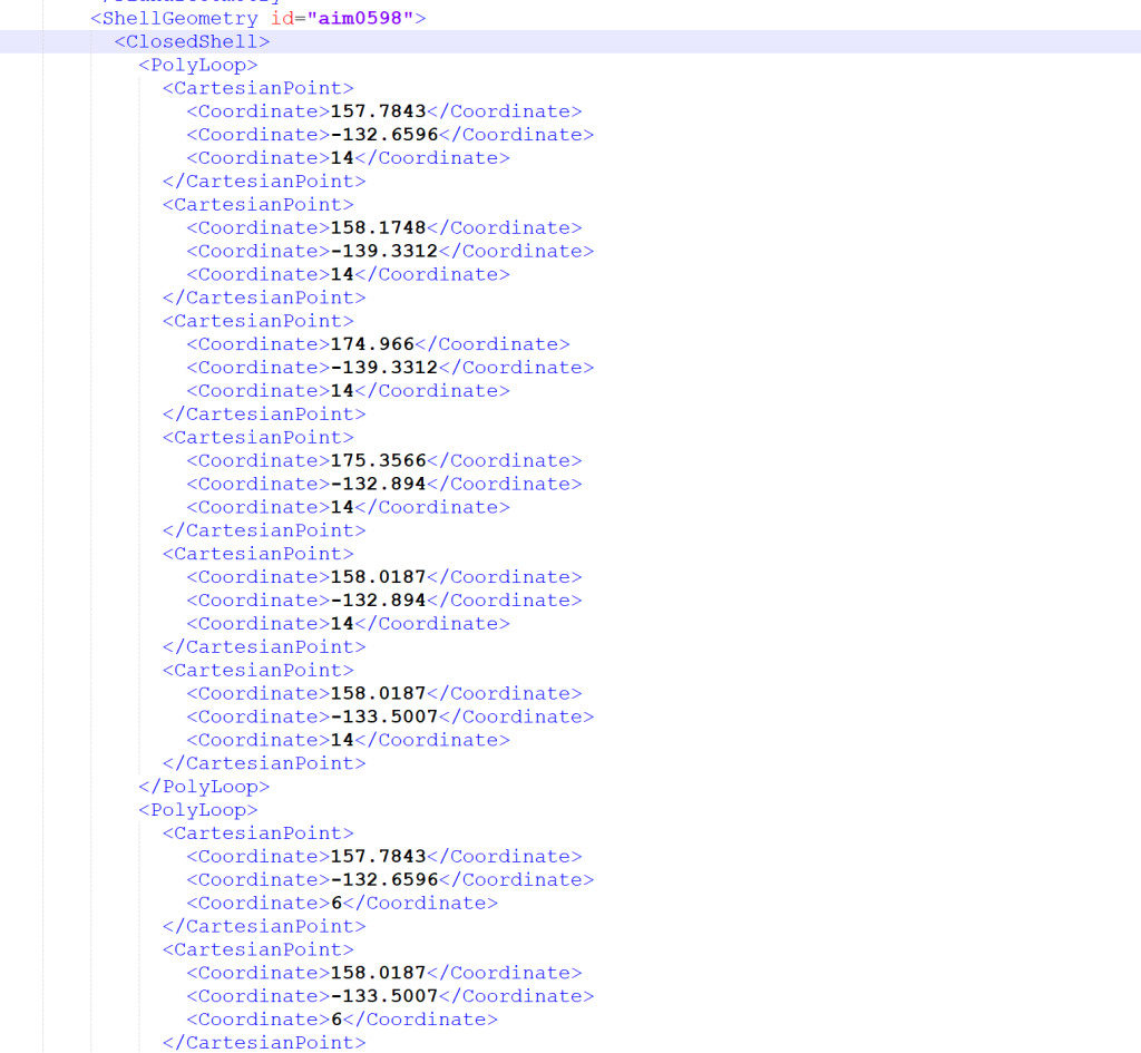
ShellGeometry: This element defines a building surface as a closed, planar, and non-intersecting 3D geometry. It can be used to represent complex shapes such as curved walls, domes, or vaults. The ShellGeometry element is typically used for building envelopes, such as walls, roofs, and floors.
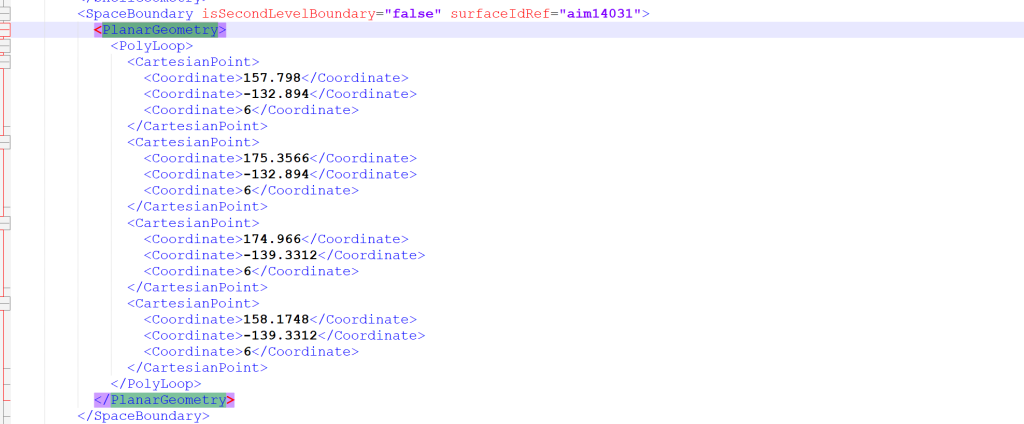
PlanarGeometry: This element defines a building surface as a flat, planar, and non-intersecting 3D geometry. It can be used to represent flat surfaces such as windows, doors, and glazing. The PlanarGeometry element is typically used for non-enveloping surfaces that have openings, such as windows or doors.
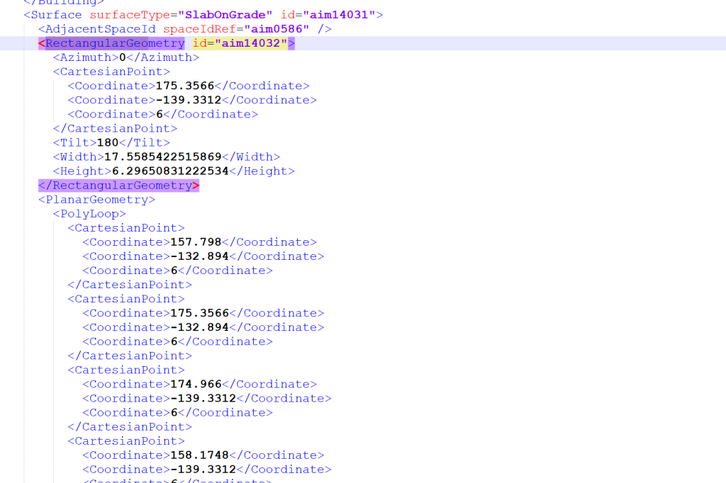
RectangularGeometry: This element defines a building surface as a rectangular, planar, and non-intersecting 3D geometry. It can be used to represent surfaces that are rectangular in shape, such as a simple flat wall. The RectangularGeometry element is typically used for simpler, regular building shapes.
In summary, the difference between these elements lies in the shape and complexity of the building surfaces they define. The ShellGeometry is used for complex and irregular shapes, PlanarGeometry is used for flat surfaces with openings, and RectangularGeometry is used for simple and regular shapes.
gbXML Viewer
In regards to the online gbXML Viewer (aka – Ladybug Tools Spider Viewer), the following elements are used:
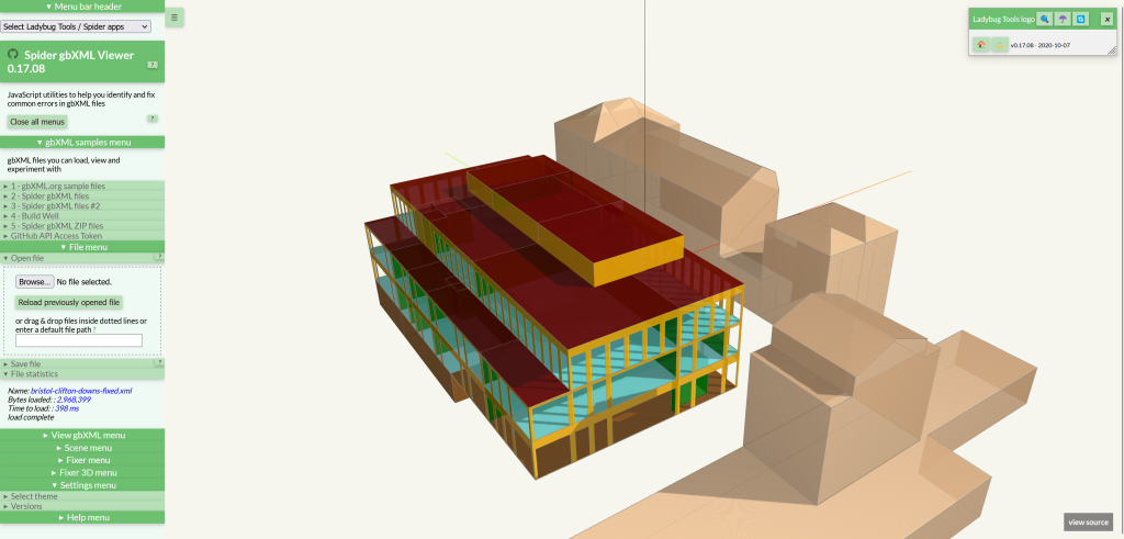
Shell Geometry: ShellGeometry data appears to have been used in older vesrions of Spider gbXML Viewer (R2) to gather surface data, and it occasionally appears in other “sandbox” files. Still, it has not been exposed to the user regularly.
Planar Geometry: PlanarGeometry data is used to gather all the coordinates in all the PolyLoops in every Surface. This data is used to draw the surfaces and openings in the gbXML Viewer.
RectangularGeometry: A popup box displays:
- All the attributes of the RectangularGeometry of the currently selected surface
- All the attributes of the RectangularGeometry of all the openings in the currently selected surface
Question 2: What are the differences between gbXML and Industry Foundation Classes (IFCs)?

Industry Foundation Classes (IFC) and gbXML are both data exchange schemas used in the architecture, engineering, and construction industry to represent building information in a structured and machine-readable format. However, there are some differences between these two standards:
Object-Oriented vs. XML-based: IFC is an object-oriented data model based on the ISO 10303 standard (also known as STEP), while gbXML is an XML-based format. This means that IFC uses a set of pre-defined objects with specific properties and behaviors, while gbXML uses a set of XML elements to represent building information.
Level of Detail: IFC is designed to represent detailed information about building elements, including their geometric, spatial, and semantic properties, which makes it suitable for use in advanced building design and construction processes such as Building Information Modeling (BIM). On the other hand, gbXML is designed to represent simpler building information, such as building geometry and thermal properties, making it more suitable for energy modeling and analysis.
Industry Adoption: IFC is widely adopted by the AEC industry as an open standard for BIM data exchange, and is supported by most major software vendors. gbXML is also widely used, but is more limited in its scope and is primarily used for energy analysis and simulation.
In summary, IFC and gbXML are both schemas used in the AEC industry for building data exchange, but they differ in their data models, level of detail, and industry adoption. IFC is more comprehensive and suitable for advanced building design and construction processes, while gbXML is more focused on energy modeling and analysis.
Also, IFCs are an ISO standard while gbXML is more a consensus standard.
Question 3: What are second-level space boundaries as it relates to energy modeling?

In the context of building design and modeling, a 2nd level space boundary (also known as a secondary space boundary) refers to a virtual boundary that separates two adjacent spaces within a building. Specifically, it defines the boundary between a space and any other adjacent spaces that are not primary enclosed spaces (i.e., spaces that have a direct contact with the outdoors or are conditioned spaces, such as rooms or corridors).
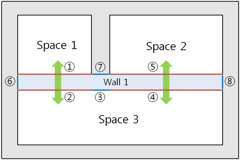
The concept of a 2nd level space boundary is important for several reasons. First, it allows building designers and engineers to more accurately model the thermal performance of a building by accounting for the heat transfer between adjacent spaces that may not have direct exposure to the outdoors. Second, it helps to define the occupancy and use of different spaces within a building, which is important for code compliance and building operation.
In a building model, a 2nd level space boundary can be defined using various methods, such as by explicitly drawing the boundary in a building design software, or by defining a set of rules that define the relationship between different spaces based on their location, orientation, and other properties. The resulting building model can then be used for various purposes, such as energy simulation, code compliance analysis, and facility management.

