Carmel Software is a member of the Board of Directors of gbXML.org which houses the Green Building XML open schema. This schema helps facilitate the transfer of building properties stored in 3D building information models (BIM) to engineering analysis tools, all in the name of designing more energy efficient buildings.
For example, an architect who is designing a building using a BIM tool such as Autodesk Revit is able to not only create the building geometry, but also assign properties to the building including lighting density, occupancy hours, wall and window properties, and much more. All of this information can be exported (or “saved-as”) as gbXML file that is then imported into a software analysis tool that predicts yearly building energy usage (such as Trane TRACE). The purpose of this integration is to eliminate the need to enter the same information into the analysis tool that is already available in the BIM tool.
It has proven so popular that almost 40 software tools world-wide have some type of gbXML integration. Click here for the list.
Recently, we have been funded by the US Department of Energy and National Renewable Energy Lab (NREL) to develop a suite of “test cases” that software vendors will need to undergo to become certified in gbXML. Certification is a process that gives vendors who produce gbXML a stamp of approval from gbXML.org:
Achieving Certification
How does a vendor achieve certification? gbXML.org has developed a series of test cases (in fact, just really simple building shapes) that each pose a new situation for the vendor to adhere to. In other words, the vendor is responsible for recreating a simple building shape in their own software tool. Then, they “save-as” gbXML and upload it to our validator software. If the building shape closely matches the test case gbXML file, then it “passes”:
What is being tested? For each test case, there are a number of items being “tested”, and it is all focused on geometry:
Are
all the surfaces in the right location and orientation?
Are
all the surfaces properly defined? Walls
are walls, floors are floors, interior/exterior etc. ?
Is
the gbXML “good”? i.e. – No typos, incorrect names, missing
fields.
Example Test Cases
Test Case 2: A window test case (see image below)
Single
window is drawn
User
converts to gbXML
Two
windows are created
Overhang
is linked to both windows.
Test Case 3: A test case for spatial configuration. If a tool was to submit for compliance, but is not touting its automated capaibilities, then the wall types would be declared explicitly and exported to gbXML and submitted for compliance.
If a tool was to submit for compliance, but is advertising automated capabilities, then the wall types would not need to be called out, and the translation to a thermal representation of the building in gbXML would happen automatically:
Test Case 5: Here is an example of a test case (see image below):
Single
volume is drawn
User
converts to gbXML
Walls
automatically separated
gbXML
shows 8 walls (4 above and below grade)
Test Case 6: If a tool was to submit for compliance, not touting automated capabilities, then the wall types would be declared explicitly, and then exported to gbXML and submitted for compliance.
If a tool was to submit for compliance, but is advertising automated capabilities, then the wall types would not need to be called out, and the translation to a thermal representation of the building in gbXML would happen automatically:
Levels of Certification
There are 3 levels of gbXML certification:
Direct translation with no automation
Basic automation where:
Surfaces are all defined and correctly converted
gbXML is valid XML
gbXML is legal gbXML as per the XSD
Advanced automation where geometry from the authoring tool to a BEM-ready model with basic automation
Level 1 and Level 2 test cases are essentially the same. The only difference is whether the tool makes it easier, through automation, to identify surface types without the user having to do it manually.
Level 3 test cases are new industry reach goals. No tools on the market today can achieve all of the Level 3 Test Cases. These are advanced benchmarks.
The total number of test cases is in flux. We expect that our user community will send emails asking for more test cases when they find a flaw in vendor software.
All test cases must be passed to achieve a full “Level 1”, “Level 2”, etc. certification.
See the image below for more information on the levels of certification.
Example of Certification Process
Our first validation customer has been the National Renewable Energy Lab (NREL). We have been working with their OpenStudio software tool which works on top of EnergyPlus to calculate yearly building energy usage. OpenStudio has enountered some difficulty in passing all of the tests. The reasons for this are two-fold:
The nature of some of the test cases are beyond OpenStudio’s intended scope
The validator has also been found to be too stringent
Some of these stringency issues include:
No allowance for metric units, or mixed metric and I-P units
Ambiguous acceptance of interior ceilings or floors
Does the azimuth and lower left hand coordinate truly have meaning for horizontal surfaces?
Handling geometry from egg-shell tools (e.g. – SketchUp, FormIt
Handling geometry from tools with Interior Surface enumeration (Bentley)
Better abstraction of wall polygons
Handling Different Types of Geometry
Handling Geometry From Egg-Shell Modelers (SketchUp, FormIt):
If all surfaces and zones are drawn on the centerline:
The surface vertices will be correct (because surface vertices are defined at the centerline)
But the area and volume calculations will be incorrect (when compared to a thick wall representation). Areas and volumes, by definition, must take into account wall thicknesses.
Solution: Tweak the validation process.
We will make special considerations for the
area and volume calculation if the vendor is
submitting for a geometry modeler like this.
Handling Geometry From Interior Surface Modelers (Bentley):
If all surfaces and zones are represented as interior:
The surface vertices will be incorrect (because surface vertices are normally defined at the centerline)
But the area and volume calculations will be correct (when compared to a thick wall representation). Areas and volumes, by definition, must take into account wall thicknesses.
Solution: Tweak the validation process.
We will make special considerations for the
area and volume calculation if the vendor is
submitting for a geometry modeler like this.
OpenStudio Validation Findings:
OpenStudio has encountered difficulty passing all the tests.
Primary:
The nature of some of the test cases are beyond OpenStudio’s intended scope
The validator has also been found to be too stringent
Secondary:
The current validation documentation could be improved, with more clarity
Validator interface could be improved to clarify why the test is passing or failing
gbXML is Proposing Changes to Simplify and Clarify Compliance:
OpenStudio has encountered difficulty passing all the tests.
Findings:
The nature of certain test cases is beyond OpenStudio’s intended scope
The validator is too stringent
Documentation needs to clarify what is being tested
Validator interface could improve to clarify why a test passed or failed
gbXML’s forward-looking position:
The number of test cases required to pass needs to decrease
The validator requirements will relax
Documentation is to be improved, and put online
Validator interface is also going to be improved to be more clear
For years, we have worked with ASHRAE to develop mobile applications related to a number of their standards and Handbook of Fundamentals chapters including ASHRAE 62.1 Standard, a duct fitting database app (which is quite popular, surprisingly), and an interactive psychrometric chart app. These apps have all helped bolster ASHRAE’s entry into the mobile age. Below are descriptions and screenshots of the various apps we have developed for ASHRAE:
Duct Fitting Database
The HVAC ASHRAE Duct Fitting Database (DFDB) app for the iPhone and iPad allows users to perform pressure loss calculations for all 243 ASHRAE fittings listed in the ASHRAE Handbook of Fundamentals.
This app is based upon the popular ASHRAE Duct Fitting Database desktop application, and you can do pretty much everything in this app that you can do in the desktop program that is offered by ASHRAE. The advantage of this mobile app is that you can easily use it out in the field to perform quick duct pressure loss calculations. The following is a list of features of this app:
You can create individual projects, each with unique input values and results.
Each fitting has its own custom set of input parameters and results
It includes a useful search feature that allows you to type in a partial or full fitting code name to quickly retrieve it.
It allows you to display and email two types of reports. These are similar to the reports available in the desktop version of the DFDB software. The app reports also include a spreadsheet attachment that you can open on your desktop computer to do further analysis.
All fittings include pictures that you can view within the app.
The app displays inputs and results in both english and metric units.
ASHRAE 62.1 App
The HVAC ASHRAE 62.1-2013 app for the iPhone allows you to perform comprehensive minimum ventilation calculations for a wide variety of commercial buildings based upon Standards 62.1-2007 and 2010/2013 (which are essentially the same). This app is based upon the “62MZCalc.xls” Excel spreadsheet that accompanies each copy of the ASHRAE 62.1 User’s Manual. You can do pretty much everything in this app that you can do in the Excel spreadsheet, in addition to creating multi-system projects and emailing results so you can perform further analysis.
ASHRAE Psychrometric Chart
The HVAC Psychrometric Chart (HVAC Psych Chart) app is the first truly interactive graphical psychrometric chart for the iPad, and it includes both IP and SI units. Using your finger, you can easily plot HVAC and other psychrometric processes on the iPad screen while out in the field, save the graphs, and then email the graph and results to clients.
It includes a number of features that allow the user to:
Customize the graph in many different ways including specifying the psychrometric chart line colors, chart background color, hide/display status of chart lines, point colors, process line colors, units of graph values, and the min/max limits of the chart
Create non-standard charts with high maximum dry-bulb temperatures or ones for high altitudes and low barometric pressures
Using a finger, plot as many points as wanted on the screen. As the user moves their finger around the graph, the psychrometric properties at the top of the screen dynamically update. In addition, users can double-tap a point to display the point properties and then edit them
ASHRAE Standard 90.1
ASHRAE 90.1 (Energy Standard for Buildings Except Low-Rise Residential Buildings) is a United States standard that provides minimum requirements for energy efficient designs for buildings except for low-rise residential buildings. Percent improvement over ASHRAE 90.1 is the basis for awarding energy points within the LEED rating system. In addition, many states apply ASHRAE 90.1 to buildings being constructed or under renovation.
There are 2 methods of complying with ASHRAE 90.1: the prescriptive and performance paths. The prescriptive path requires that all components of the building meet the minimum standards specified by ASHRAE 90.1. The performance path involves modeling the proposed building design and demonstrating (through building energy simulation) that it uses less energy than a baseline building built to ASHRAE 90.1 specifications. In the performance path approach, a baseline Energy Cost Budget (ECB) is established, based on the building size and program.
Section 11 of Standard 90.1 describes the ECB Method, an alternative approach to demonstrating compliance of a building design with Standard 90.1. Compliance with Section 11 is described in detail in Section 11.1.4 of the standard. With the ECB Method, a computer program is used to calculate the design energy cost for the proposed building design and to calculate the energy cost budget for a budget building design. In the budget building design, which is a variant of the proposed building design, all mandatory and prescriptive requirements of the Standard are applied. In other words, the energy cost budget represents the building as if it complied with the Standard. The design energy cost for the proposed design cannot exceed the energy cost budget.
This standard has always confounded us in terms of determining the best type of app or software tool to develop for it, and that’s ASHRAE Standard 90.1. ASHRAE 90.1 is such a comprehensive and wide ranging standard for building energy efficiency that is hard to develop just one software tool that will “automate” everything needed by stakeholders. We’ve talked with ASHRAE Publications for years and even created a joint SurveyMonkey to gauge interest in the type of software tool that would best serve the 90.1 community. Here are a couple of screenshots of the questions and responses from the SurveyMonkey:
Based upon the responses from the survey above and talking with members of the ASHRAE 90.1 standards committee, we decided to develop a software tool to aid in filling out the 90.1 Energy Cost Budget method (ECB) compliance form located on page 395 of the ASHRAE 90.1-2010 User’s Manual. At first, we were contemplating developing a mobile app for iOS, but then received feedback that most users would not use it in the field. Therefore, we decided to develop a web app that would work on any device (laptop, iOS, or Android) as long as it was connected to the Internet. This would allow users to easily use it in the office and in the field.
The web app that we developed is based upon a variation of the ECB forms that start on page 395 of the User’s Manual. The altered forms were developed into the form of an Excel spreadsheet by Greg McCall of Vancouver, Canada. The variations in the spreadsheet have helped better tailor the forms toward building code officials. For example, it breaks down the energy end use and fuel type sections into building, parkade, and site/other sections that allow for more intelligible categorization by space type within the building. In addition, the spreadsheet includes a number of statistical values that help code officials visualize the relationships between the different values.
The following two images are the ECB forms from the User’s Manual:
The 90.1 ECB website allows users to export all of the information and calculated results to an Excel spreadsheet in the exact same format as Greg McCall’s original spreadsheet. From this exported spreadsheet, you can alter values, export reports to PDF, and print reports. Below is a sample of the statistics page in the web app:
While not everyone is utilizing the standard by implementing the ECB method, this web application is a good start to digitizing the ASHRAE 90.1 standard. The link to the ASHRAE 90.1 website is here: https://901ecb.ashrae.org.
Overview
We have developed a number of equipment selection software tools over the years. While this type of software is not the sexiest type of software out there and its user-base is quite small compared to games or word processors, we feel that this type of software is quite interesting to develop. I’d like to share a bit about our experiences with developing 2 different types of equipment software selection tools for several large HVAC manufacturing companies.
Definition
What is equipment selection software exactly? It is a computerized or digital tool that allows users to properly choose the correct HVAC manufacturer’s model equipment based upon a wide variety of input and/or output parameters. Depending upon the type of equipment, the parameters can vary greatly. For example, HVAC humidification equipment requires input parameters such as outdoor weather conditions, elevation, indoor air temperature and humidity, and required outlet air conditions.
Users of this type of software include HVAC engineers, manufacturers representatives, and manufacturer salespeople. These tools can be web, tablet, or desktop based software applications.
Mitsubishi Electric
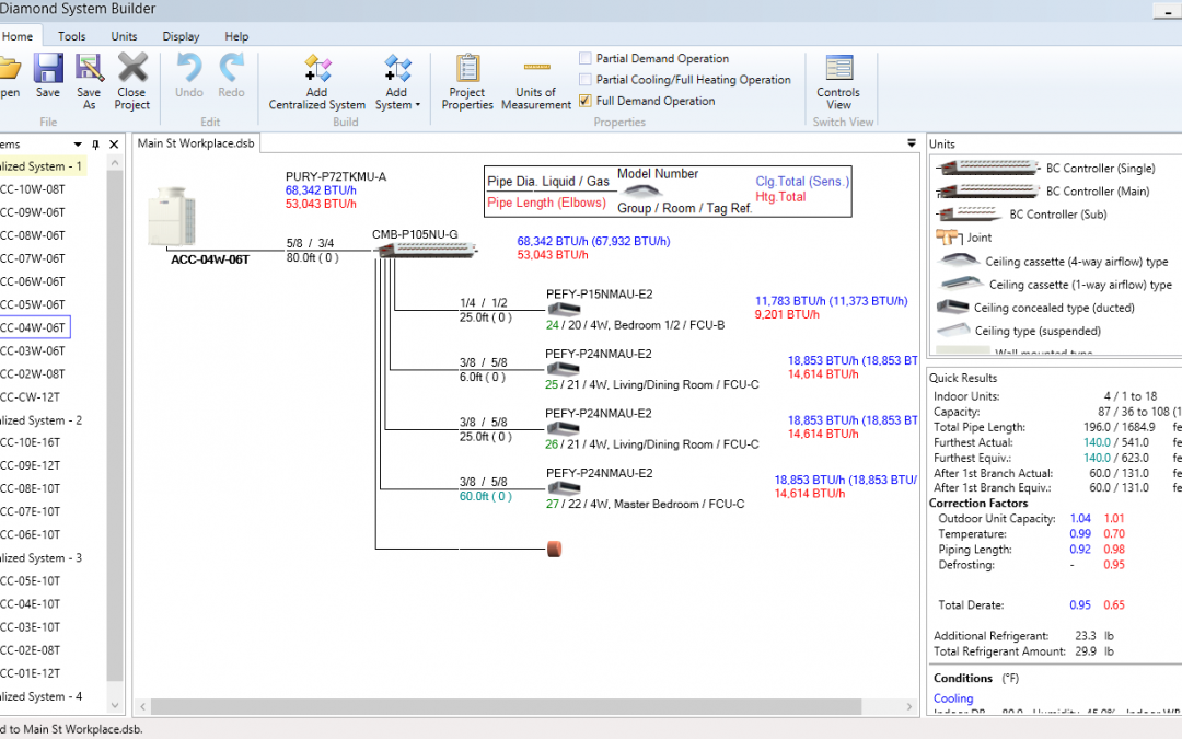
We were hired by Mitsubishi Electric (ME) of America to develop an equipment selection desktop software tool for their line of VRF (variable refrigerant flow) HVAC equipment. They insisted that the tool have a graphically intensive user interface with lots of drag-and-drop functionality. The software tool would allow users to lay out a schematic of the VRF system including the outdoor unit, indoor units, connectors, pipes, and other components. The tool would be strictly rule-based so it would inform the user as to whether a certain length of pipe was allowed or if a certain model outdoor unit could be paired with a specific indoor unit. The types of outputs were numerous including PDF reports, AutoCAD schematics, spreadsheet outputs, XML, and even proprietary file format output to a Mitsubishi controller.
Other functionality included the ability to dynamically update and add new equipment model information, localization include language and regional models for different areas of the world, and ability to layout controls wiring.
This projected took about 3 years to fully develop and finally deploy to end users including Mitsubishi engineers, resellers, and salespeople.
Some takeaways from this project:
1. It took much longer to develop than originally planned (no surprise, here). Between changing requirements and long approval waiting periods, the timeline almost tripled.
2. Localizing software tools is a very complex endeavor. It not only involves translation files for one or more languages, but it also involves filtering equipment selections depending upon the region of the world. Also, numerical values must be displayed in English or Metric units depending upon the region.
3. Integrating with popular third-party software tools such as AutoCAD is a never ending process since there are so many versions of AutoCAD that it is impossible to universally integrate with all of the versions. Therefore, a number of users who have incompatible versions of the tool are not able to utilize the functionality.
Advantix Systems
Advantix Systems is an HVAC manufacturer of dehumidification equipment. They have a patented, liquid desiccant technology that both cools and dehumidifies simultaneously, eliminating the need to overcool the air to control humidity. It’s actually quite ingenious, and the image below shows how this works:
This image courtesy of Advantix Systems: http://www.advantixsystems.com/how_it_works_more_efficient.php
As you can see from the psychrometric chart, dehumidification occurs without having to ride the saturation curve (green versus purple). This is an amazing engineering accomplishment, since now there is no need to waste energy on reheating the temperature from the saturation curve to the required dehumidification point.
Advantix Systems hired Carmel Software to develop a web-based equipment selection software tool that would allow reps and engineers to quickly select and price equipment based upon required conditions. Features included:
Creating a quick rating of a product (or set of products) given inlet conditions (airflow, temperature, humidity) and an Advantix model number. It would display product performances (decrease in temperature and moisture removal, outlet conditions, energy removed (total and latent).
Creating a quick selection of equipment under specific conditions (temperature, humidity, airflow, desired outlet temperature and humidity or desired temperature decrease and moisture removal) and allow the user to select from 1 or more models that satisfy the required outlet conditions
Creating guided selections that ask the user a number of leading questions that tell the software which models are most appropriate
Providing relevant PDF submittal documentation for selected equipment
Ability to manage equipment performance, documentation and options by either editing or adding new equipment.
Key Takeaways
This was an extremely complicated project due to a number of factors including:
It was extremely calculation intensive. Not only were there complex psychrometric calculations, but complicated logic to select the most optimal equipment either by efficiency or cost standards. In other words, we weren’t done after the basic psych calcs. There was a lot more to do after calculating the outlet conditions including develop complex logic to iterate through 100s of scenarios to determine the optimal equipment configuration.
There were lots of reporting requirements requested by the client. Not only were we dynamically generating PDF submittals, but also drawing elevation-specific psychrometric charts with all process points and lines.
As is a common theme here and with almost all specialty software development companies, this project took far longer than originally planned by either parties. This was mainly due to changing requirements and complex logic that far exceeded our expectations.
Overview
We’ve been lucky enough to receive a number of contracts over the past couple of years to develop “Internet of Things (IoT)” mobile applications that communicate with a variety physical devices such as pressure-temperature gauges, refrigerant scales, and blower-testing devices.
We’ve just completed a contract with Uniweld Products, a U.S. manufacturing company, that manufacturers welding, HVAC/R, and many other types of meters and gauges. Over the past 3 years, we have been working with Precision Diagnostic Instruments, who is working with Uniweld Products, to develop an Android-based mobile app that does two things:
Performs HVAC refrigerant charge calculations (subcool and superheat) for over 75 different refrigerants
Communicates with an HVAC refrigerant charge meter device using BLE (Bluetooth Low Energy).
This device measures subcool and superheat temperatures and pressures from an HVAC unit and displays those values within the app and performs other calculations.
From a software development perspective, this was quite a complex project since it involved three main modules:
The software user interface
The BLE (bluetooth) communication interface
The refrigerant charge calculation engine
Software User Interface
The software user interface was specified by the client. The provided samples of what they were looking for, and we were able to replicate exactly what they requested. There are a number of different screens in the app including:
The “home” screen is accessed after connecting to the gauge. This screen displays the subcool or superheat information in an easy-to-read format.
This Settings form allows the user customize the app:
The user can select from a number of different refrigerants:
BLE (Bluetooth) Communication Interface
The SmarTech App uses a BroadcastReceiver and ServiceConnection to form bluetooth communication between the Meter and Android Device. The ServiceConnection handles the devices connection to the meter. BroadcastReceiver listens for changes in the bluetooth state and acts accordingly based on the state. The information received from the meter is sent over as a series of bytes that the Android Device is able to read.
Calculation Engine
The refrigerant charge calculation engine performs superheat and subcool refrigerant charge calculations for 75 different refrigerants. The user inputs the indoor wet-bulb and outdoor dry-bulb temperatures to get the target superheat temperature. Then, the user specifies the suction line temperature and pressure to get the actual superheat temperature. The difference tells the user whether they need to charge or not. Also, if the user selected an azeotropic refrigerant (like R-403A (Bubble)), then it will automatically use the “Dew” version of R-403A for superheat calculations. To perform subcool refrigerant charge calculations for 100+ different refrigerants, the user inputs the indoor wet-bulb and outdoor dry-bulb temperatures to get the target subcool temperature. Then, the user specifies the liquid line temperature and pressure to get the actual subcool temperature. The difference tells the user whether to charge or not. Also, if the user selected an azeotropic refrigerant (like R-403A (Dew)), then it will automatically use the “Bubble” version of R-403A for superheat calculations.
Lessons Learned
Like many software development projects, this project took far longer to complete than originally anticipated. This was due to a number of reasons including:
Complexities of Bluetooth communication protocols: The development time of Bluetooth communication functionality with an external measuring device should never be underestimated. The complexity of the protocols along with the idiocyncracies of hardware devices can quadruple the amount of time it takes to develop such an app. Next time, we will budget more time (and money) toward this effort.
Accommodating all of the different types of Android devices: There are many different types of smartphones and tablets that run the Android operating system. Many of these devices have different screen sizes that need to be accommodated for (including the ability to display in both portrait and landscape modes). When negotiating with a client, it is best to set expectations that the app will only be optimized for 1 or 2 different screen sizes.
Carmel Software is a member of the Board of Directors of gbXML.org which houses the Green Building XML open schema. This schema helps facilitate the transfer of building properties stored in 3D building information models (BIM) to engineering analysis tools, all in the name of designing more energy efficient buildings.
Here is a more layman’s explanation of what this all means:
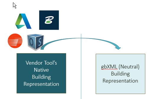
Green Building XML (gbXML) is a schema or “language” that allows BIM (building information modeling) authoring software tools such as Autodesk Revit to communicate with building analysis tools such as Trane TRACE.
For example, a user is able to design a 3D virtual model of a building in Autodesk Revit. This model includes complete visual geometry of the building and information about the types of walls, windows, roofs, lighting and occupancy density. Since this information is required by building energy analysis software tools, it is redundant to re-enter all of it into a stand-alone energy analysis software tool when it is readily available from the 3D model. This is where gbXML helps: A software tool such as Autodesk Revit is able to “Save As” gbXML meaning that it is able to export all of its geometry and other building information into the gbXML language format. Taking this gbXML file, the user is now able to “import” this building information into software tools such as EnergyPlus or Trane Trace without manually re-entering all of this data by hand. The end result of all of this is that an energy modeler is better able to design more energy efficient buildings for purposes of, say, LEED certification.
In theory, the above workflow sounds seamless and attractive to anyone involved with modeling the energy usage of a building. In reality, the process is fraught with enough complications that energy modelers often forego this process in favor of more manual methods. These complications result from inconsistencies in how the various software tools integrate with gbXML.
Today, gbXML has the industry support of leading 3D BIM vendors such as Autodesk, Bentley, and Graphisoft. In addition, we have been funded in the past by the US Department of Energy and its various labs to further develop the gbXML schema and also better market it to industry stakeholders.
In the Fall of 2015, the National Renewable Energy Laboratory (NREL) agreed to fund Carmel Software to further improve the gbXML schema in the following ways:
1. Carmel will develop OpenStudio (NREL’s cross-platform
collection of software tools to support whole building energy modeling
using EnergyPlus) models which represent the buildings in the validation procedure test case developed in Phase I. These models will be generated programmatically using the OpenStudio Ruby Application Programming Interface (API) to reduce maintenance costs and to allow them to be leveraged for other purposes.
2. Carmel will improve the validation website, documentation, and tools required to apply the validation procedure. Carmel will publicize the validation procedure and encourage gbXML software vendors to apply it to their tools.
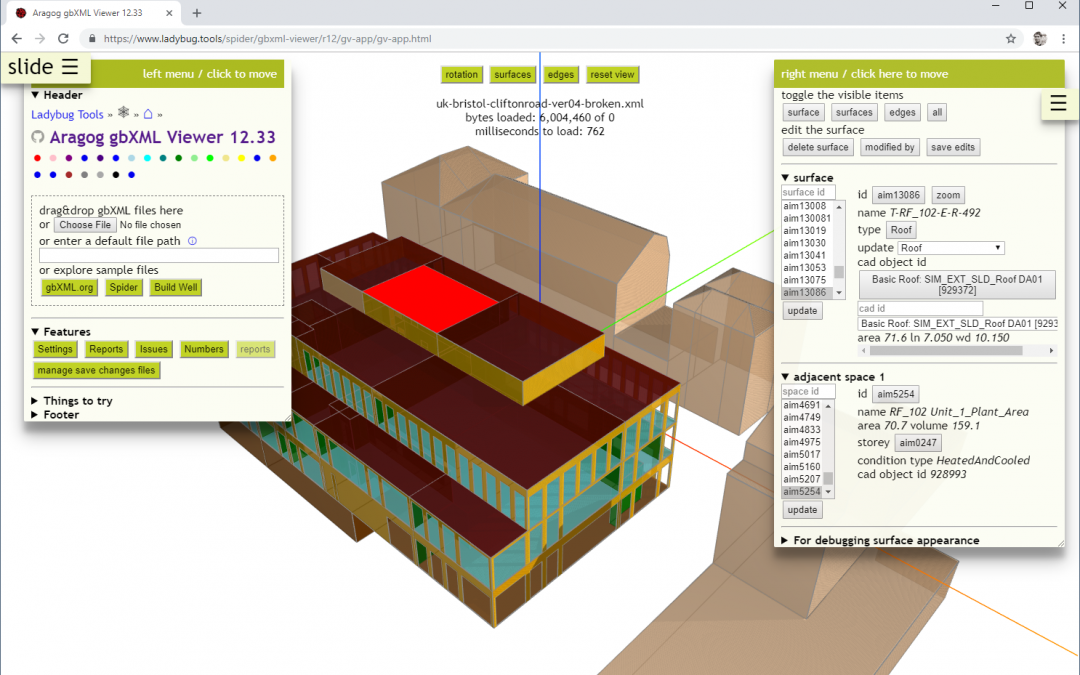
3. Carmel will apply the technologies developed for the validation procedure to a general use validation tool. This tool will be able to validate any generic gbXML file and, it will also include a web-based 3D model viewer.
This will be a 9 month project scheduled for completion in September 2016. We will be presenting results at the SimBuild 2016 Conference in Salt Lake City.
Carmelsoft have been accepted to the Autodesk Cloud Accelerator program from March 14 to 18, 2016 in San Francisco, CA at Autodesk’s 1 Market Street facility. During the Accelerator, we will be working intensively on a specific project to integrate our mobile apps with the Autodesk Forge platform with the help, support and training of the Autodesk Cloud Engineering team. By the end of the week, we hope to have a working
prototype in-hand.
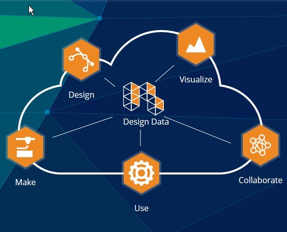
The Autodesk Forge platform is a set of Autodesk Cloud Services, APIs and SDKs for developers to create data, apps, and services that integrate with some of Autodesk’s cloud offerings. The Forge platform includes tools that:
Visualize: Interactively visualize data, create photo-real renderings and generate 3D models from your apps.
Collaberate: Application APIs for project and file access. SDKs to extend Autodesk Cloud Services with collaboration workflows.
Make: Turn designs into physical reality.
Use: Connect, analyze, control, and manage remote products, things, and assets.
The following is a list of Autodesk’s cloud APIs:
BIM 360 – Collaborative construction management softwareBIM 360™ construction management software enables almost anytime, anywhere access to project data throughout the building construction lifecycle.
BIM 360 Glue – BIM ManagementBIM 360™ Field is field management software for 2D and 3D environments that combines mobile technologies at the construction site with cloud-based collaboration and reporting.
Recap 360 – Reality capture and 3D scanning software Infraworks 360 – Preliminary engineering with data-rich 3D models
Fusion 360 – A new approach to industrial and mechanical 3D design
View & Data Cloud Services – Integrated viewing, search and data
AutoCAD I/O – For developers who want to process DWG files at cloud scale.
We will be taking advantage of the View and Data API. This API allows users to create custom web applications that enable customers to visualize and interact with 2D and 3D design data in a web browser or on a mobile device. The API supports over 60 file formats to bring detailed, high-fidelity visualizations of models. We will be integrating our HVAC ResLoad-J and Equipment Locator apps with the View and Data API so users can view building CAD drawings within these apps so as to easily extract geometric information. We’ll discuss more in future blog posts.
 Certification")
 Certification")
 Certification")
 Certification")
 Certification")
 Certification")
 Certification")
 Certification")
 Certification")
 Certification")


")
")
")
")